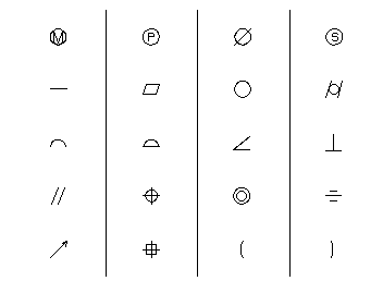
Standard ANSI symbols for form and positional tolerance, material condition, etc. may be obtained by using one of the special control characters or numbers.
|
Control Character |
Symbol |
|
M |
Maximum material condition |
|
S |
Regardless of feature size |
|
P |
Projected tolerance zone |
|
O |
Diameter (where O is a capital letter). |
|
&1 |
Straightness |
|
&2 |
Flatness |
|
&3 |
Circularity |
|
&4 |
Cylindricity |
|
&5 |
Profile of Line |
|
&6 |
Profile of Surface |
|
&7 |
Angularity |
|
&8 |
Perpendicularity |
|
&9 |
Parallelism |
|
&10 |
True position |
|
&11 |
Concentricity |
|
&12 |
Symmetry |
|
&13 |
Circular runout |
|
&14 |
Rectangularity |
|
&15 |
Total runout |
|
( |
A left parenthesis 2 times the current character size. For reference dimensions, etc. |
|
) |
A right parenthesis 2 times the current character size. For reference dimensions, etc. |
|
+ |
A perpendicular divider with the size the same as the frame size of the form and positional tolerance symbol. |
|
<#aN> |
Quantity (where N is a number) |
|
<#b> |
Counterbore/Spotface |
|
<#c> |
Countersink |
|
<#d> |
Depth |
|
<#e> |
Conical taper |
|
<#f> |
Square |
|
<#g> |
Slope |
|
<O> |
Diameter (where O is a capital letter) |
|
S<O> |
Spherical diameter (where O is a capital letter) |
This example demonstrates the use of control characters to create drafting and dimensioning symbols.
&ENSITE=&TOPL
NOTE/-2.2, 1.5,$
'<M> <+>
<P> <+> <N>',$
'<O> <+> <S>'
NOTE/-2.2, .8,$
'<&1>
<+> <&2> <+> <N>',$
'< &3 > < + >
< &4 >'
NOTE/-2.2, .1,$
'<&5>
<+> <&6> <+> <N>',$
'<&7> <+>
<&8>'
NOTE/-2.2, -.6,$
'<&9>
<+> <&10> <+> <N>',$
'<&11> <+>
<&12>'
NOTE/-2.2,-1.3,$
'<&13>
<+> <&14> <+> <N>',$
'<(> <+>
<)>'

Drafting Symbols and Characters Created by Control Characters